تست و کنترل مدل سه بعدی با mpu6050
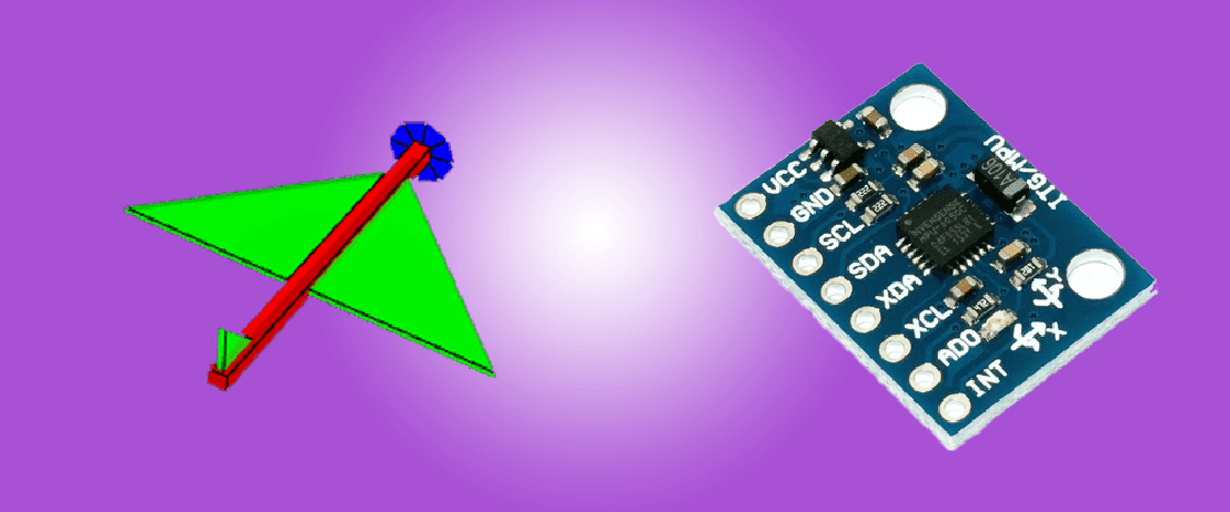
در این آموزش از ساخت پروژه نحوه تست و کنترل مدل سه بعدی با ماژول شتاب سنج و ژیروسکوپ MPU6050 و اردینو را اموزش خواهیم داد. ابتدا من نحوه تست ماژول MPU6050 و بعد نحوه کنترل مدل سه بعدی با mpu6050 توضیح خواهم داد
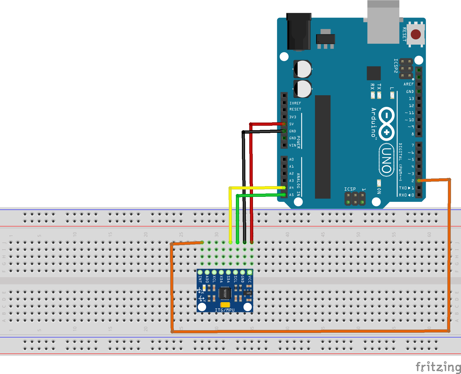
شماتیک تست و کنترل مدل سه بعدی با mpu6050
SCL ماژول mpu6050 به پایه A5 اردوینو
SDA ماژول mpu6050 به پایه A4 اردوینو
INT ماژول mpu6050 به پایه 2 اردوینو
VCC ماژول به پایه 5V اردوینو
GND ماژول به پایه GND اردوینو
کد تست ماژول mpu6050
برای تست ماژول کد های زیر رو کپی و در نرم افزار پیست کنید و روی اردوینو اپلود کنید
#include <Wire.h>
const int MPU = 0x68;
float AccX, AccY, AccZ;
float GyroX, GyroY, GyroZ;
float accAngleX, accAngleY, gyroAngleX, gyroAngleY, gyroAngleZ;
float roll, pitch, yaw;
float AccErrorX, AccErrorY, GyroErrorX, GyroErrorY, GyroErrorZ;
float elapsedTime, currentTime, previousTime;
int c = 0;
void setup() {
  Serial.begin(19200);
  Wire.begin();
  Wire.beginTransmission(MPU);
  Wire.write(0x6B);
  Wire.write(0x00);
  Wire.endTransmission(true);

  calculate_IMU_error();
  delay(20);
}
void loop() {
  Wire.beginTransmission(MPU);
  Wire.write(0x3B);
  Wire.endTransmission(false);
  Wire.requestFrom(MPU, 6, true);
  AccX = (Wire.read() << 8 | Wire.read()) / 16384.0;
  AccY = (Wire.read() << 8 | Wire.read()) / 16384.0;
  AccZ = (Wire.read() << 8 | Wire.read()) / 16384.0;
  accAngleX = (atan(AccY / sqrt(pow(AccX, 2) + pow(AccZ, 2))) * 180 / PI) - 0.58;
  accAngleY = (atan(-1 * AccX / sqrt(pow(AccY, 2) + pow(AccZ, 2))) * 180 / PI) + 1.58;
  previousTime = currentTime;
  currentTime = millis();
  elapsedTime = (currentTime - previousTime) / 1000;
  Wire.beginTransmission(MPU);
  Wire.write(0x43);
  Wire.endTransmission(false);
  Wire.requestFrom(MPU, 6, true);
  GyroX = (Wire.read() << 8 | Wire.read()) / 131.0;
  GyroY = (Wire.read() << 8 | Wire.read()) / 131.0;
  GyroZ = (Wire.read() << 8 | Wire.read()) / 131.0;
  // Correct the outputs with the calculated error values
  GyroX = GyroX + 0.56; // GyroErrorX ~(-0.56)
  GyroY = GyroY - 2; // GyroErrorY ~(2)
  GyroZ = GyroZ + 0.79; // GyroErrorZ ~ (-0.8)
  gyroAngleX = gyroAngleX + GyroX * elapsedTime; // deg/s * s = deg
  gyroAngleY = gyroAngleY + GyroY * elapsedTime;
  yaw =  yaw + GyroZ * elapsedTime;

  roll = 0.96 * gyroAngleX + 0.04 * accAngleX;
  pitch = 0.96 * gyroAngleY + 0.04 * accAngleY;

  // Print the values on the serial monitor
  Serial.print(roll);
  Serial.print("/");
  Serial.print(pitch);
  Serial.print("/");
  Serial.println(yaw);
}
void calculate_IMU_error() {
  while (c < 200) {
    Wire.beginTransmission(MPU);
    Wire.write(0x3B);
    Wire.endTransmission(false);
    Wire.requestFrom(MPU, 6, true);
    AccX = (Wire.read() << 8 | Wire.read()) / 16384.0 ;
    AccY = (Wire.read() << 8 | Wire.read()) / 16384.0 ;
    AccZ = (Wire.read() << 8 | Wire.read()) / 16384.0 ;
    // Sum all readings
    AccErrorX = AccErrorX + ((atan((AccY) / sqrt(pow((AccX), 2) + pow((AccZ), 2))) * 180 / PI));
    AccErrorY = AccErrorY + ((atan(-1 * (AccX) / sqrt(pow((AccY), 2) + pow((AccZ), 2))) * 180 / PI));
    c++;
  }
  AccErrorX = AccErrorX / 200;
  AccErrorY = AccErrorY / 200;
  c = 0;
  while (c < 200) {
    Wire.beginTransmission(MPU);
    Wire.write(0x43);
    Wire.endTransmission(false);
    Wire.requestFrom(MPU, 6, true);
    GyroX = Wire.read() << 8 | Wire.read();
    GyroY = Wire.read() << 8 | Wire.read();
    GyroZ = Wire.read() << 8 | Wire.read();
    // Sum all readings
    GyroErrorX = GyroErrorX + (GyroX / 131.0);
    GyroErrorY = GyroErrorY + (GyroY / 131.0);
    GyroErrorZ = GyroErrorZ + (GyroZ / 131.0);
    c++;
  }
  GyroErrorX = GyroErrorX / 200;
  GyroErrorY = GyroErrorY / 200;
  GyroErrorZ = GyroErrorZ / 200;
  Serial.print("AccErrorX: ");
  Serial.println(AccErrorX);
  Serial.print("AccErrorY: ");
  Serial.println(AccErrorY);
  Serial.print("GyroErrorX: ");
  Serial.println(GyroErrorX);
  Serial.print("GyroErrorY: ");
  Serial.println(GyroErrorY);
  Serial.print("GyroErrorZ: ");
  Serial.println(GyroErrorZ);
}
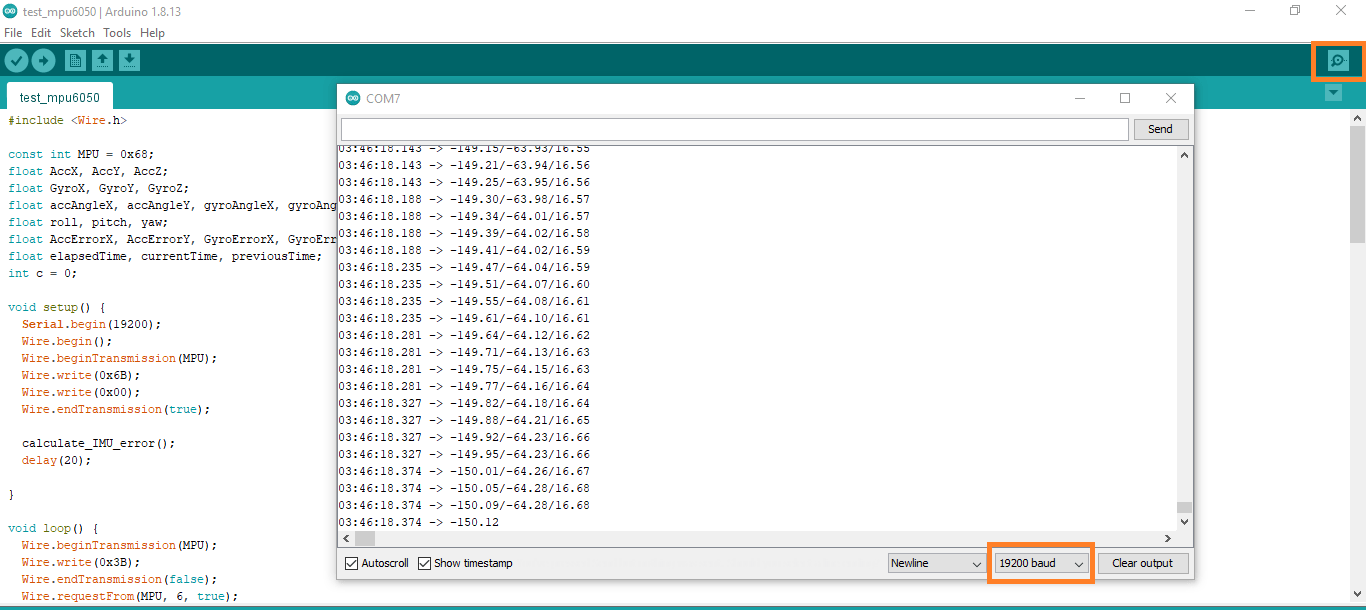
بعد از اپلود کد ، سریال مانیتور رو باز کنید و سرعت روی 19200 قرار دهید در صورتی که ماژول سالم باشه و با تغییر موقعیت ماژول در محور های x , y مدل مقادیر نیز تغییر می کند.
کنترل مدل سه بعدی با mpu6050
ابتدا کتابخانه mpu6050 رو از اینجا دانلود کنید و به اردوینو اضاف کنید
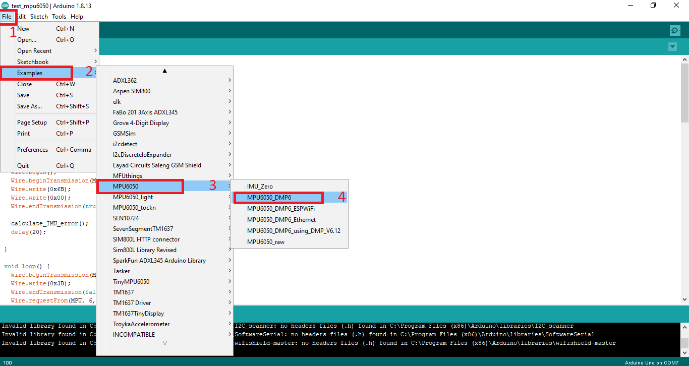
بعد مطابق با تصویر زیر مثال زیر را اجرا کنید
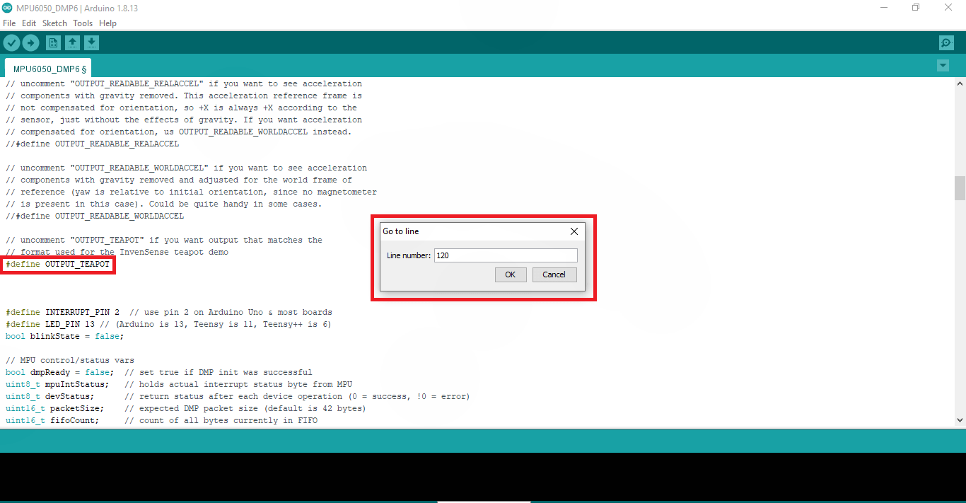
حال باید تغییراتی در این کد ایجاد کنیم با استفاده از Ctrl+L، پنجره ای برای جستجوی شماره خط کد خواهید دید، خط ۱۲۰ را جستحو کنید، مانند تصویر زیر کد مربوط به teapot را از اسلش خارج و سپس کد را روی اردوینو آپلود کنید.
در ادامه برای نمایش مدل سه بعدی ابتدا اخرین ورژن نرم افزار Processing از اینجا دانلود و نصب کنید
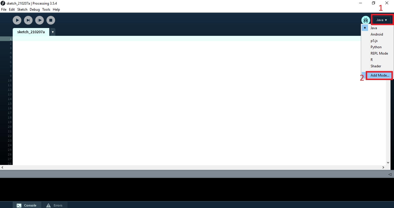
نرم افزار رو اجرا کنید و مطابق با تصویر زیر ابتدا روی java و بعد رو add mode کلیک کنید
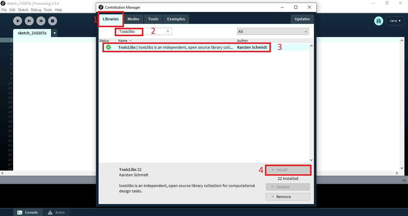
در صفحه باز شده مطابق تصویر زیر به قسمت کتابخانه بیاید کتابخانه Toxiclibs سرچ کنید و بعد نصب کنید
بعد کد زیر را کپی کنید و در Processing پیست کنید
// I2C device class (I2Cdev) demonstration Processing sketch for MPU6050 DMP output
// 6/20/2012 by Jeff Rowberg <jeff@rowberg.net>
// Updates should (hopefully) always be available at https://github.com/jrowberg/i2cdevlib
//
// Changelog:
//     2012-06-20 - initial release
/* ============================================
I2Cdev device library code is placed under the MIT license
Copyright (c) 2012 Jeff Rowberg
Permission is hereby granted, free of charge, to any person obtaining a copy
of this software and associated documentation files (the "Software"), to deal
in the Software without restriction, including without limitation the rights
to use, copy, modify, merge, publish, distribute, sublicense, and/or sell
copies of the Software, and to permit persons to whom the Software is
furnished to do so, subject to the following conditions:
The above copyright notice and this permission notice shall be included in
all copies or substantial portions of the Software.
THE SOFTWARE IS PROVIDED "AS IS", WITHOUT WARRANTY OF ANY KIND, EXPRESS OR
IMPLIED, INCLUDING BUT NOT LIMITED TO THE WARRANTIES OF MERCHANTABILITY,
FITNESS FOR A PARTICULAR PURPOSE AND NONINFRINGEMENT. IN NO EVENT SHALL THE
AUTHORS OR COPYRIGHT HOLDERS BE LIABLE FOR ANY CLAIM, DAMAGES OR OTHER
LIABILITY, WHETHER IN AN ACTION OF CONTRACT, TORT OR OTHERWISE, ARISING FROM,
OUT OF OR IN CONNECTION WITH THE SOFTWARE OR THE USE OR OTHER DEALINGS IN
THE SOFTWARE.
===============================================
*/
import processing.serial.*;
import processing.opengl.*;
import toxi.geom.*;
import toxi.processing.*;
// NOTE: requires ToxicLibs to be installed in order to run properly.
// 1. Download from http://toxiclibs.org/downloads
// 2. Extract into [userdir]/Processing/libraries
//    (location may be different on Mac/Linux)
// 3. Run and bask in awesomeness
ToxiclibsSupport gfx;
Serial port;                         // The serial port
char[] teapotPacket = new char[14];  // InvenSense Teapot packet
int serialCount = 0;                 // current packet byte position
int synced = 0;
int interval = 0;
float[] q = new float[4];
Quaternion quat = new Quaternion(1, 0, 0, 0);
float[] gravity = new float[3];
float[] euler = new float[3];
float[] ypr = new float[3];
void setup() {
    // 300px square viewport using OpenGL rendering
    size(300, 300, OPENGL);
    gfx = new ToxiclibsSupport(this);
    // setup lights and antialiasing
    lights();
    smooth();

    // display serial port list for debugging/clarity
    println(Serial.list());
    // get the first available port (use EITHER this OR the specific port code below)
    //String portName = Serial.list()[0];

    // get a specific serial port (use EITHER this OR the first-available code above)
    String portName = "COM7";

    // open the serial port
    port = new Serial(this, portName = "COM7" , 115200);

    // send single character to trigger DMP init/start
    // (expected by MPU6050_DMP6 example Arduino sketch)
    port.write('r');
}
void draw() {
    if (millis() - interval > 1000) {
        // resend single character to trigger DMP init/start
        // in case the MPU is halted/reset while applet is running
        port.write('r');
        interval = millis();
    }

    // black background
    background(0);

    // translate everything to the middle of the viewport
    pushMatrix();
    translate(width / 2, height / 2);
    // 3-step rotation from yaw/pitch/roll angles (gimbal lock!)
    // ...and other weirdness I haven't figured out yet
    //rotateY(-ypr[0]);
    //rotateZ(-ypr[1]);
    //rotateX(-ypr[2]);
    // toxiclibs direct angle/axis rotation from quaternion (NO gimbal lock!)
    // (axis order [1, 3, 2] and inversion [-1, +1, +1] is a consequence of
    // different coordinate system orientation assumptions between Processing
    // and InvenSense DMP)
    float[] axis = quat.toAxisAngle();
    rotate(axis[0], -axis[1], axis[3], axis[2]);
    // draw main body in red
    fill(255, 0, 0, 200);
    box(10, 10, 200);

    // draw front-facing tip in blue
    fill(0, 0, 255, 200);
    pushMatrix();
    translate(0, 0, -120);
    rotateX(PI/2);
    drawCylinder(0, 20, 20, 8);
    popMatrix();

    // draw wings and tail fin in green
    fill(0, 255, 0, 200);
    beginShape(TRIANGLES);
    vertex(-100,  2, 30); vertex(0,  2, -80); vertex(100,  2, 30);  // wing top layer
    vertex(-100, -2, 30); vertex(0, -2, -80); vertex(100, -2, 30);  // wing bottom layer
    vertex(-2, 0, 98); vertex(-2, -30, 98); vertex(-2, 0, 70);  // tail left layer
    vertex( 2, 0, 98); vertex( 2, -30, 98); vertex( 2, 0, 70);  // tail right layer
    endShape();
    beginShape(QUADS);
    vertex(-100, 2, 30); vertex(-100, -2, 30); vertex(  0, -2, -80); vertex(  0, 2, -80);
    vertex( 100, 2, 30); vertex( 100, -2, 30); vertex(  0, -2, -80); vertex(  0, 2, -80);
    vertex(-100, 2, 30); vertex(-100, -2, 30); vertex(100, -2,  30); vertex(100, 2,  30);
    vertex(-2,   0, 98); vertex(2,   0, 98); vertex(2, -30, 98); vertex(-2, -30, 98);
    vertex(-2,   0, 98); vertex(2,   0, 98); vertex(2,   0, 70); vertex(-2,   0, 70);
    vertex(-2, -30, 98); vertex(2, -30, 98); vertex(2,   0, 70); vertex(-2,   0, 70);
    endShape();

    popMatrix();
}
void serialEvent(Serial port) {
    interval = millis();
    while (port.available() > 0) {
        int ch = port.read();
        if (synced == 0 && ch != '$') return;   // initial synchronization - also used to resync/realign if needed
        synced = 1;
        print ((char)ch);
        if ((serialCount == 1 && ch != 2)
            || (serialCount == 12 && ch != '\r')
            || (serialCount == 13 && ch != '\n'))  {
            serialCount = 0;
            synced = 0;
            return;
        }
        if (serialCount > 0 || ch == '$') {
            teapotPacket[serialCount++] = (char)ch;
            if (serialCount == 14) {
                serialCount = 0; // restart packet byte position

                // get quaternion from data packet
                q[0] = ((teapotPacket[2] << 8) | teapotPacket[3]) / 16384.0f;
                q[1] = ((teapotPacket[4] << 8) | teapotPacket[5]) / 16384.0f;
                q[2] = ((teapotPacket[6] << 8) | teapotPacket[7]) / 16384.0f;
                q[3] = ((teapotPacket[8] << 8) | teapotPacket[9]) / 16384.0f;
                for (int i = 0; i < 4; i++) if (q[i] >= 2) q[i] = -4 + q[i];

                // set our toxilibs quaternion to new data
                quat.set(q[0], q[1], q[2], q[3]);
                /*
                // below calculations unnecessary for orientation only using toxilibs

                // calculate gravity vector
                gravity[0] = 2 * (q[1]*q[3] - q[0]*q[2]);
                gravity[1] = 2 * (q[0]*q[1] + q[2]*q[3]);
                gravity[2] = q[0]*q[0] - q[1]*q[1] - q[2]*q[2] + q[3]*q[3];

                // calculate Euler angles
                euler[0] = atan2(2*q[1]*q[2] - 2*q[0]*q[3], 2*q[0]*q[0] + 2*q[1]*q[1] - 1);
                euler[1] = -asin(2*q[1]*q[3] + 2*q[0]*q[2]);
                euler[2] = atan2(2*q[2]*q[3] - 2*q[0]*q[1], 2*q[0]*q[0] + 2*q[3]*q[3] - 1);

                // calculate yaw/pitch/roll angles
                ypr[0] = atan2(2*q[1]*q[2] - 2*q[0]*q[3], 2*q[0]*q[0] + 2*q[1]*q[1] - 1);
                ypr[1] = atan(gravity[0] / sqrt(gravity[1]*gravity[1] + gravity[2]*gravity[2]));
                ypr[2] = atan(gravity[1] / sqrt(gravity[0]*gravity[0] + gravity[2]*gravity[2]));

                // output various components for debugging
                //println("q:\t" + round(q[0]*100.0f)/100.0f + "\t" + round(q[1]*100.0f)/100.0f + "\t" + round(q[2]*100.0f)/100.0f + "\t" + round(q[3]*100.0f)/100.0f);
                //println("euler:\t" + euler[0]*180.0f/PI + "\t" + euler[1]*180.0f/PI + "\t" + euler[2]*180.0f/PI);
                //println("ypr:\t" + ypr[0]*180.0f/PI + "\t" + ypr[1]*180.0f/PI + "\t" + ypr[2]*180.0f/PI);
                */
            }
        }
    }
}
void drawCylinder(float topRadius, float bottomRadius, float tall, int sides) {
    float angle = 0;
    float angleIncrement = TWO_PI / sides;
    beginShape(QUAD_STRIP);
    for (int i = 0; i < sides + 1; ++i) {
        vertex(topRadius*cos(angle), 0, topRadius*sin(angle));
        vertex(bottomRadius*cos(angle), tall, bottomRadius*sin(angle));
        angle += angleIncrement;
    }
    endShape();

    // If it is not a cone, draw the circular top cap
    if (topRadius != 0) {
        angle = 0;
        beginShape(TRIANGLE_FAN);

        // Center point
        vertex(0, 0, 0);
        for (int i = 0; i < sides + 1; i++) {
            vertex(topRadius * cos(angle), 0, topRadius * sin(angle));
            angle += angleIncrement;
        }
        endShape();
    }

    // If it is not a cone, draw the circular bottom cap
    if (bottomRadius != 0) {
        angle = 0;
        beginShape(TRIANGLE_FAN);

        // Center point
        vertex(0, tall, 0);
        for (int i = 0; i < sides + 1; i++) {
            vertex(bottomRadius * cos(angle), tall, bottomRadius * sin(angle));
            angle += angleIncrement;
        }
        endShape();
    }
}
در خط 74 و 77 مطابق با تصویر زیر شماره عدد رو تغییر دهید و عدد com اردوینو خودتان قرار دهید
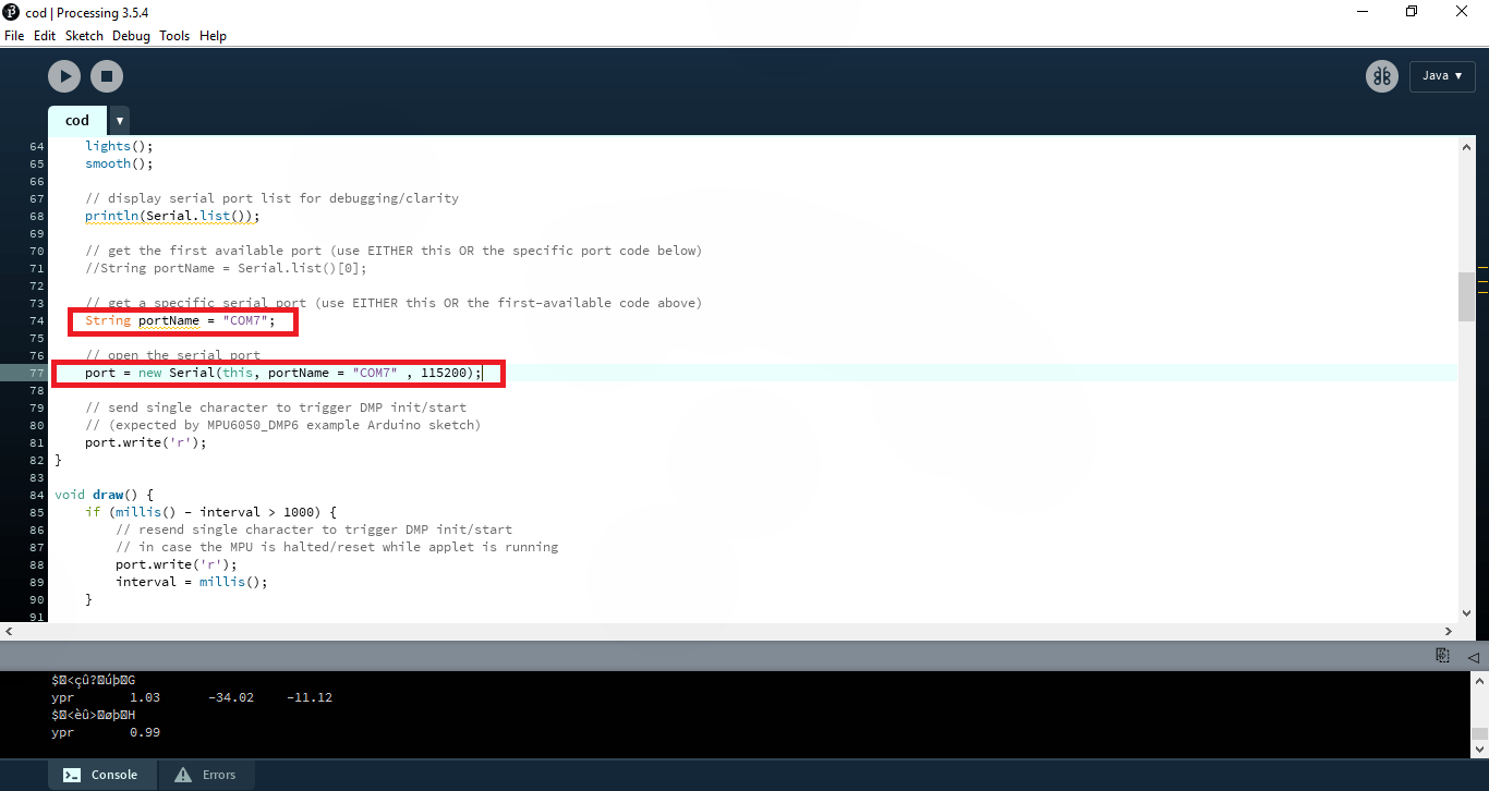
و در اخر مطابق تصویر زیر روی Run کلیک کنید
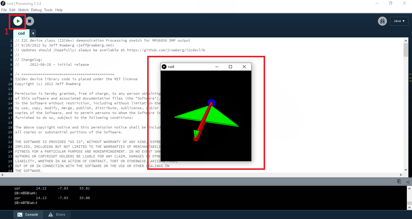
بعد از کلیک روی Run برایتان پنجره جدیدی باز خواهد شد که مدل 3D در آن نمایش داده می شود. و با موقعیت ماژول در محور های x , y مدل سه بعدی نیز تغییر می کند.
